Flying Wing
Glider
Aerodynamic Analysis & Optimization
Design Objective
Optimized glider for performance and payload requirements
Flying Wing Glider is an aerospace engineering group project completed as part of the Aerospace Practicum class. The objective was to design, analyze, and optimize various glider configurations to meet specific payload and size requirements while maximizing aerodynamic performance.
As part of the design team, I performed comprehensive elementary aerodynamic calculations including Reynolds number analysis to characterize flow regimes, lift coefficient (CL) determination for wing performance, drag coefficient (CD) estimation for efficiency optimization, and sink rate calculations to evaluate glide performance under various operating conditions.
The design process involved endurance analysis to maximize flight duration, comparative evaluation of multiple glider configurations, and iterative optimization to identify the design that delivered the best overall performance while satisfying mission requirements. CAD modeling using NX Siemens and technical drawing generation supported fabrication planning and design validation.
Performance Calculations
Quantitative assessment of flight characteristics
Reynolds Number
Calculated Reynolds number to characterize flow regime around the glider airfoil. Determined whether flow would be laminar, transitional, or turbulent to inform drag predictions and boundary layer behavior.
Lift Coefficient
Analyzed lift coefficient across various angles of attack and flight conditions. Evaluated wing planform efficiency and airfoil selection to maximize lift generation while maintaining stable flight characteristics.
Drag Coefficient
Computed total drag including parasitic drag (form drag, skin friction) and induced drag. Optimized wing aspect ratio and airfoil geometry to minimize drag and maximize glide ratio.
Sink Rate Analysis
Determined vertical descent rate at various forward speeds. Identified minimum sink rate operating point to maximize flight endurance and extend glide distance for payload delivery missions.
Development Methodology
Iterative design and analysis workflow
Requirements Definition
Established mission requirements including payload capacity, size constraints, and performance objectives. Defined success metrics: glide ratio, endurance, and structural integrity.
Conceptual Design
Developed multiple glider configurations including conventional, flying wing, and canard designs. Performed preliminary sizing and weight estimation for each concept.
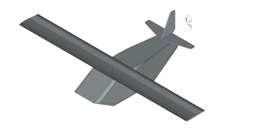
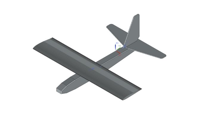
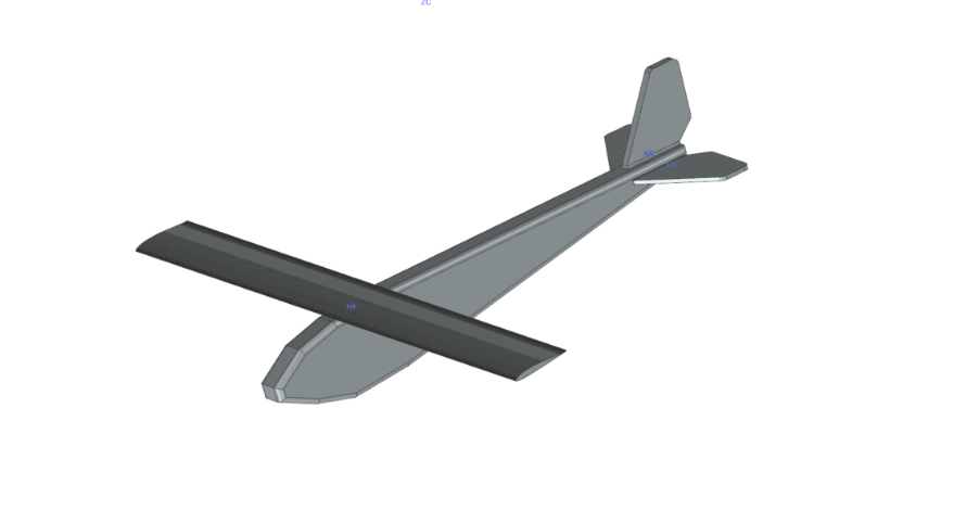
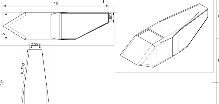
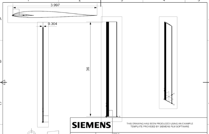
CAD Modeling
Created detailed 3D CAD models using NX Siemens software for each design variant. Generated technical drawings with dimensions, material specifications, and assembly instructions.
Design Optimization
Iteratively refined wing geometry, aspect ratio, and airfoil selection to maximize L/D ratio. Balanced competing requirements of low drag, adequate lift, and structural simplicity.
Design Selection
Compared all design variants against performance criteria. Selected optimal configuration that met payload and size requirements while delivering best aerodynamic performance.
Aerodynamic Calculations
Executed elementary aerodynamic analysis for final design. Calculated Reynolds number, lift coefficient, drag coefficient, sink rate, and endurance to validate performance predictions.
CAD Models & Drawings
Design visualization and engineering specifications
Skills Demonstrated
Engineering analysis and design capabilities